|
|
|
|
|
| 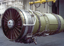 |
My research topic
At the end of 2003 I was interested on studying a Master, I began my major studies, Microelectronic Master, in January 2004. I am in the Control Specialization working with my tutor Dr. Igor Loboda in the Gas Turbine Parametric Diagnostics. I have been learning about the most basic turbine parts, their components and functions, covering the inlet, the compressor, the combustion chamber, the turbine and the outlet, including the external systems such as, fuel system, oil system and starting system. All of this has been examined in order to guide the research of the Diagnostic of the Gas Turbine involving Control and Diagnostic. At the same time I have been taking other lessons like Linear Control, covering topics such as, Method to solve Differential Equations, Different Responses of a System, System Equilibrium, Lyapunov Stability, Relative Degree, Stability Criterion of Bode and Nyquist and Controlability and Observability of a Transfer Function. In the other hand, I have been taking the Simulation and Programming subject I have learned how to use the Matlab software, programs and functions, in this I have covered topics like Relational Operators, Cycles (for, while), Basics Commands, read and write of flat file text, sampling of voice signals and filtering and rotation of images. Another subject is Mathematics Topics and I have been working with Statistics and Probability covering topics such as, Relative Frequency, Conditional Probability, Bayes Theorem, Probability Adding Theorem, Discrete and Continuous Variables, Probability Density Function, Chebyshev Inequality and Rayleigh Distribution.
In the Gas Turbine Diagnostic I will try to find, solve or even predict faults applying the domain of the Software Engineering and as a core of this Neural Networks. In this complex machines we can have a variety of faults, taking into account that the faults are according of the complexity of the machine. I will expose some of the situations found in this engine and examples of engine performance monitoring, from the compressor part to the turbine part.
In recent years, a method of monitoring the gas turbine engine�s day to day condition has been adopted by many operators. In this system the EPR, Engine Pressure Ratio, EGT, Exhaust Gas Temperature, and throttle position are used to determine the aerodynamic performance of the engine, while vibration amplitude and oil consumption (which may include periodic spectrometric oil analysis) is used to evaluate mechanical performance. Although specific procedures will vary from operator to operator, in general, cockpit instrument readings are taken once a day or on every flight during cruise conditions. The recorded data is then processed in a variety of ways and compared with �normal� data established by the manufacturer or the operator as representing the normal performance of the engine. Engine performance monitoring is proving to be a very effective method of providing early warning information of ongoing or impending failures, thus reducing unscheduled delays and more serious engine failures.
A number of compressor section failures may be broadly classified as failures resulting in the leakage of high-pressure air form the compressor section of the engine. This leakage may be due to the failure of a bleed air duct external to the engine, a stuck overboard bleed valve, or failure of the engine casing itself. In the cruise operating range, where engine monitoring is done, the turbine expansion ratio of the engine is fixed. Engine pressure ratio is therefore directly related to the pressure ratio across the compressors. The leakage of air form the compressor causes the compression ratio, and consequently the EPR, to drop if the throttle position is not changed. To regain EPR, the throttle is pushed further forward, increasing the fuel flow. This in turn increases the turbine inlet temperature, power generated by the turbine section, and rotor speeds. The increased power to drive the compressors will regain the compression ratio in spite of the air leak. Therefore, air leaks in the compressor section generally result in the plots where all of the monitored performance parameters increase.
Air leakage may occur between the high and low compressors, at some intermediate stage, or from the diffuser case. This air may be discharged into the nacelle, overboard or into the fan duct. The magnitude of change in the engine parameters is dependent of all the aforementioned factor plus the size of the leak.
Engine performance will decrease due to compressor contamination. Contamination of the compressor may occur due to operation near salt water, the use of impure water for water injection, an oil leak in the forward part of the engine that may cause fine dust to adhere to the blades, or contamination from ingestion during reversing. Often the effects of compressor contamination can be eliminated bye water washing or carboblasting the engine. Contamination of the compressor blades changes their aerodynamic shape, roughens their surfaces, and reduces the airflow area. Reduced airflow area in turn reduces compressor efficiency and airflow capacity. When the compressors required to achieve the desired compressor pressure ratio and hence EPR. This additional power is obtained by pushing the throttle further forward, increasing fuel flow, an increasing turbine inlet temperature.
The increase in speed of the low compressor relative to the increase in speed of the high compressor will be influenced by the type of contamination and whether the contaminations is in the low-pressure compressor, high-pressure compressor, or both. Water contamination resulting from inlet water injection, for instance, normally settles out in the high-pressure compressor. Little or none of these deposits form on the low-pressure compressor. This difference is due to the combination of temperature and pressure existing in the high compressor, plus the time element involved in vaporizing the water.
Generally speaking, of all the engine sections, the burner section is the least sensitive to failure detection using in-flight monitoring techniques. The majority of the combustion section problems experienced in the operation of an engine include failures such as blocked fuel nozzles, fuel line leaks, and failure of a burner can itself. Usually these problems must be detected by maintenance monitoring methods. It is only when the problem becomes severe enough to affect another section of the engine that in-flight monitoring becomes useful. The section most often affected by burner failures is the turbine section. Pieces of the combustion chamber that become loose and eventually break away will most often cause some sort of damage farther down the gas path. In some cases, the flame pattern becomes distorted sufficiently to burn or bow the inlet guide vanes immediately after of this section. This explains why monitoring plots of failures that include damage to the burner section most often resemble high-pressure turbine failures.
Engine performance monitoring has proved to be very useful in detecting trouble areas in the high-pressure turbine. For example, loss of a first-stage turbine blade will most likely cause a makes shift in several of the performance parameters, whereas a similar single blade loss in either of the compressors could possibly go undetected. There are relatively few blades in the system to develop the work required to drive the high-pressure compressor and a slight loss in turbine efficiency will be quite noticeable in engine operating performance. This sensitivity also applies to the components such as inlet guide vanes and turbine seals that also influence the turbine efficiency. It is not possible to determine exact parameter shifts for failures in the high-pressure turbine. The degree of failure, the compounding effects of secondary damage to the low-pressure turbine, an the compressor and fuel-control design determine the degree of performance change in each case. However, a general pattern usually appears in cases involving only the high-pressure turbine. A loss of turbine efficiency (broken blade or seal erosion) or an effective increase in turbine to absorb less than the designed amount of work, resulting in a drop in N2. For a given EPR, more energy is required and, therefore, fuel flow and EGT increase. The change in N1 is usually insignificant. The conditions applying to the low-pressure turbine are much the same as the high-pressure turbine except that the work-per-blade ratio is quite a bit smaller. For this reason, the low-pressure turbine is less responsive to in-flight monitoring. Furthermore, damage to the low-pressure turbine is caused in most cases by debris from upstream failures. The general pattern to be expected in failures affecting only the low-pressure turbine are the reverse of those described above. That is, N1 ,power 1, normally shows a marked decrease. EGT and fuel flow again increase. Power N2 will increase in this case, however, the increase may be slight.
All of these situations present in the Gas Turbine have to be Controlled by specialized software systems as long as applying the Control Theory and of course, knowing the whole function of the machine. It is necessary to make simulations and modeling to analyze the performance of the unit. In this way it is obviously necessary to study subjects such as: Software Engineering, Neural Networks and Linear, No Linear and Digital Control and Applied Modeling with Mathematics, in order to complete the research.
Nowadays as a UEC student in Tokyo, Japan, I want to continue with the well realization of my selected issue to get the degree. Before coming to UEC my supervisor, Dr. Igor Loboda, and me agreed to improve my general knowledge in Neural Network, and Dra. Mariko Nakano Miyatake recommended me to work with the Dr. Nakano.
|