
Page 47 - 2024F
P. 47
40 UEC Int’l Mini-Conference No.53
Micromechanical Simulation Using Discrete and Finite
Elements Applied to Soil Liquefaction
Gamaliel Jeevan Dewanto, Kanata Yamashita, Hans-Georg Matuttis, Department of Me-
chanical Engineering and Intelligent systems, The University of Electro-Communications
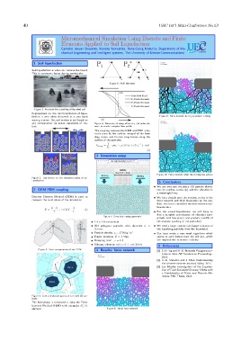
1 Soil liquefaction
Soil liquefaction is when soil behave like liquid.
This is commonly found during earthquake.
Figure 5: FEM elements
Figure 1: Fountain-like upwelling of liquefied soil
Explanations on the micromechanics of lique-
faction is very often discussed in a very hand Figure 9: Force network during pavement sinking
waving manner: the soil motion is not based on
any computation via actual equations of mo- Figure 6: Necessity of using effectively 3rd order ele-
tion. ment to resolve complex flow profile
The coupling between the DEM and FEM is ba-
sicaly done by the surface integral of the form
drag forces and friction drag forces along the
outline of the particles.
Z
T
F drag = −pδ ij + µ((∇u) + (∇u) ) · ˆndl
Γ
(2)
3 Simulation setup
Figure 10: Force network after the sinking has settled
Figure 2: Our theory on the micromechanics of soil
liquefaction
5 Conclusions
We can simulate the setup (10 particle diame-
2 DEM-FEM coupling ters for outflow seems ok) and the vibration in
a meaningful way.
Discrete Element Method (DEM) is used to We have already seen the inverted arches in the
compute the solid phase of the simulation. force network and their dissolution at the out-
flow: this is our candidate mechanism for actual
E · A √ ˙ A liquefaction.
F = + γ mY · (1)
l l For the actual liquefaction, we still have to
find a suitable combination of vibration (am-
Figure 7: Simulation setup geometry
plitude and frequency) and porosity (width of
1.5 x 1.5 cm domain the shadow, packing of the particles).
504 polygonal particles with diameter d = We need a larger system size (larger distance of
0.5mm the liquefying particles from the boundary).
Particle density, ρ = 2700kg/m 3 Our boss wrote a new mesh algorithm which
Elastic modulus, E = 1 Mpa seems to work better than the old one, which
Damping coef. , c = 0.5 will improve the numerical stability.
Sideway vibration u(t) = 0.1 · sin(10πt)
5 References
Figure 3: Force computation of the DEM 4 Results: force network [1] S. H. Ng and H.-G. Matuttis Polygonal par-
ticles in fluid, AIP Conference Proceedings,
2013.
[2] H.-G. Matuttis and J. Chen Understanding
the discrete element method, Wiley, 2014.
[3] Jan Mueller Investigation of the Liquefac-
tion of Fluid Saturated Granular Media with
a Combination of Finite and Discrete Ele-
ments, PhD Thesis, 2022.
Figure 4: Core and shadow approach to model 2D par-
ticles
The fluid phase is simulated is using the Finite
+
Element Method (FEM) with triangular P P 1
2
element. Figure 8: Initial force network
1