Å@
Go to Yiam's Room
|
Å@ Go to Yiam's Room |
Steps that I
used to build my pc
|
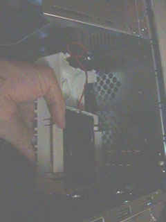
Step4. Install the exhaust fan As processor technology pushes to faster speeds and higher performance, the higher volume of heat is dissipated. It is recommended that you should install fan as much as possible to drive the heat from your your case.
Photo 1. Install the exhuast fan in front of the case
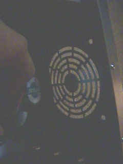
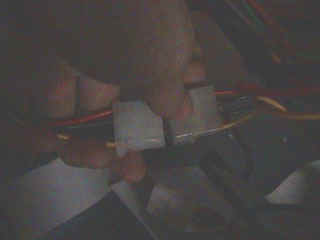
Photo 2. Install the exhust fan in the rear of the case There is a pass-through cable for the exhaust cooling fan. This cable has male and female connectors as shown in Photo 3, so that it is only installed one way.
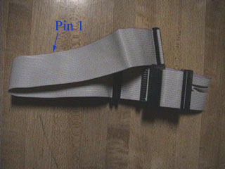
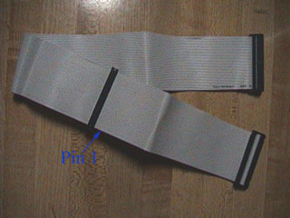
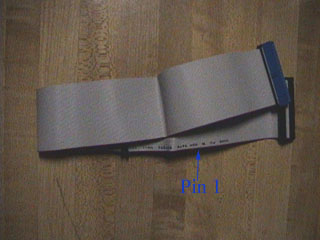
Photo 3. Power cable pass-through for the exhaust fan Step5. Get familiar with your drive cables Before installing your basic devices (Harddrive, DVD (or CD) drive, Floopy drive) , you should become familiar with the cables that are used with those various drives. When you bought the retailer-boxed mother board, you will usually have 3 different types of cables; floppy drive cable, UDMA-33 (regular IDE) cable and UDMA-66 (ATA-66) cable. Photo 4, "Floppy drive cable", shows the logic cable that is plugged into the floppy disk drive. Notice that the cable has a twisted wire between the connectors and has a red or blue stripe on the right side. This stripe mates with the pin 1 side of the cable connect oon the floppy drive. Also, the width of the connector is smaller than those of UDMA33 and UDMA66.
Photo 4. Floppy drive cable Photo 5, "UDMA-33 (Regular IDE) cable", shows a cable that is usually used to connect with the secondary drives such as DVD (or CD) drive, ZIP drive, or LS-120 drive. Compared with the UDMA-66 cable, the UDMA-33 cable has 40 wires which are obviously thicker. Though, the number of pins of both connectors are the same as 40 pins, and both cables may have a red marking for the pin 1 side, otherwise a key to ease you to get them correctly plugged in.
Photo 5. UDMA-33 (Regular IDE) cable Photo 6, "UDMA-66 (ATA66) cable", shows a cable that is genarrally plugged into the primary drives such as the harddrive. The UDMA-66 cable has 80 wires which are much thinner than those of UDMA-33 cable. (See more details in Photo 2.)
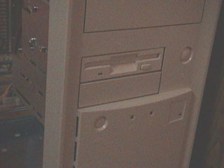
Photo 6. UDMA-66 (ATA66) cable Step6. Install FDD Install the floppy drive into the appropriate location in the case as shown in Photo 7.
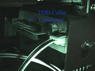
Photo 7. Flopy drive in the case Plug "Floppy drive cable" shown in Photo 4 and the power cable into the back of the floppy drive as shown in Photo 8. Make sure that the red stripe of the cable mates with the pin 1 side of the cable connector on the floppy drive. Photo 8. Plug the power cable and floppy cable |
Get paid while you are surfing the net!! Click here

| lawti-k@fedu.uec.ac.jp |