Go to Yiam's Room
|
Å@ Go to Yiam's Room |
Steps that I
used to build my pc
|
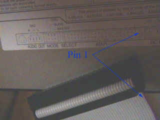
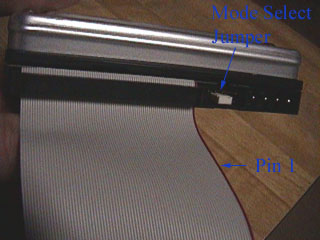
Step7. Install DVD Like step 6, you now install the DVD drive into the case. To choose the location, you should rather check the length of your Regular IDE cable. Choose the location that your cable could get connection of the DVD drive and motherboard. Also, check the mode select jumpers which are 6 straight angle pins located on the rear of the DVD-ROM. By placing a jumper on the pins, you can select the following functions:
In most installations, jumper should remain in the MA position (factory default). It is
recommended that you install your DVD-ROM only on the secondary IDE BUS. If you are
installing on primary IDE BUS, your hard drive would then be the Master, and you should
set your DVD-ROM to the Slave position (SL) Plug "Regular IDE cable" shown in Photo 5 and the power cable into the back of the DVD drive. As shown in Photo 9., Make sure that the red stripe of the cable mates with the pin 1 side of the cable connector on the DVD drive. Photo 9. Confirm the stripe of the IDE cable to the connector After installing Floppy and DVD drives, you will get your case like the photo 10. Photo 10. Floppy drive and DVD drive Like installing DVD Drive, you have to check the jumper in the rear of the harddisk drive whether it was on MA position before installing. Also, plug "ATA/66 cable" shown in Photo 6 and the power cable into the rear of the drive as shown in Photo 11. Make sure that the red stripe of the cable mates with the pin 1 side of the cable connector on the HDD drive.
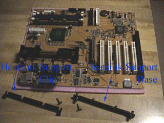
Photo 11. Installing HDD Step9. Install heatsink support assembly Photo 12 shows the parts of the heatsink support assembly. The heatsink support base installs on the mother board serves to provide a stable base for the processor module heatsink. The legs of the heatsink support base are different sizes. You can only install the heatsink support base oriented in one direction. The heatsink support clip attaches the heatsink to the heatsink support base after the processor module has been installed in the motherboard. The mounting holes for the heatsink support base are roughly indicated by the two arrows in Photo 12. Position the heatsink support base in the mounting holes with the larger leg of the base in the larger hole of the mother board.
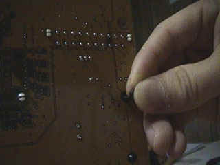
Photo 12. The Heatsink Support Assembly After positioning the heatsink support base on the top of the motherboard, turn the motherboard over and insert the two retaining pins through the bottoms of the heatsink support base legs as shown in Photo 13.
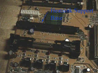
Photo 13. Inserting the pin to the leg of heatsink Photo 14. shows the heatsink support base properly installed on a motherboard. Leave the heatsink support clip off the support base until later in this procedure.
Photo 14. Top of Motherboard, Installing the Heatsink Support |
Get paid while you are surfing the net!! Click here

| lawti-k@fedu.uec.ac.jp |