
Page 42 - 2025S
P. 42
UEC Int’l Mini-Conference No.54 35
verify that dynamic performance criteria remain
satisfied. Finally, the cleaned and validated
topologies are exported in both VTK and PNG
formats for visualization and downstream man-
ufacturing. This sequence ensures that the opti-
mized designs are not only high-performance but
also directly manufacturable via additive man-
ufacturing, without the need for manual inter-
vention.
4 Experimental Setup
4.1 Benchmark Problem
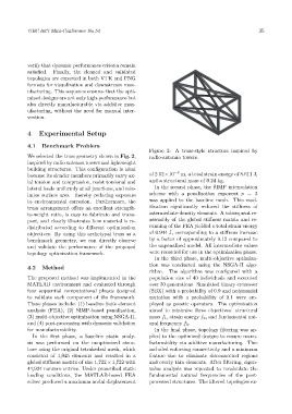
Figure 2: A truss-style structure inspired by
We selected the truss geometry shown in Fig. 2, radio-antenna towers.
inspired by radio antenna towers and lightweight
building structures. This configuration is ideal
because its slender members primarily carry ax- of 2.52×10 −3 m, a total strain energy of 8.611 J,
ial tension and compression, resist torsional and and a structural mass of 0.24 kg.
lateral loads uniformly at all junctions, and min- In the second phase, the SIMP interpolation
imize surface area—thereby reducing exposure scheme with a penalization exponent p = 3
to environmental corrosion. Furthermore, the was applied to the baseline mesh. This mod-
truss arrangement offers an excellent strength- ification significantly reduced the stiffness of
to-weight ratio, is easy to fabricate and trans- intermediate-density elements. A subsequent re-
port, and clearly illustrates how material is re- assembly of the global stiffness matrix and re-
distributed according to different optimization running of the FEA yielded a total strain energy
objectives. By using this archetypal truss as a of 0.944 J, corresponding to a stiffness increase
benchmark geometry, we can directly observe by a factor of approximately 9.12 compared to
and validate the performance of the proposed the unpenalized model. All intermediate values
topology optimization framework. were recorded for use in the optimization phase.
In the third phase, multi-objective optimiza-
tion was conducted using the NSGA-II algo-
4.2 Method
rithm. The algorithm was configured with a
The proposed method was implemented in the population size of 40 individuals and executed
MATLAB environment and evaluated through over 30 generations. Simulated binary crossover
four sequential computational phases designed (SBX) with a probability of 0.9 and polynomial
to validate each component of the framework. mutation with a probability of 0.1 were em-
These phases include: (1) baseline finite element ployed as genetic operators. The optimization
analysis (FEA), (2) SIMP-based penalization, aimed to minimize three objectives: structural
(3) multi-objective optimization using NSGA-II, mass f 1 , strain energy f 2 , and fundamental nat-
and (4) post-processing with dynamic validation ural frequency f 3 .
for manufacturability. In the final phase, topology filtering was ap-
In the first phase, a baseline static analy- plied to the optimized designs to ensure manu-
sis was performed on the unoptimized struc- facturability via additive manufacturing. This
ture using the original tetrahedral mesh, which included enforcing connectivity and a minimum
consisted of 1,045 elements and resulted in a feature size to eliminate disconnected regions
global stiffness matrix of size 1,722 × 1,722 with and overly thin elements. After filtering, eigen-
44,924 nonzero entries. Under prescribed static value analysis was repeated to recalculate the
loading conditions, the MATLAB-based FEA fundamental natural frequencies of the post-
solver produced a maximum nodal displacement processed structures. The filtered topologies ex-