
Page 11 - 2024F
P. 11
4 UEC Int’l Mini-Conference No.53
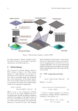
Figure 1: Measurement diagram 1 based on FTP.
scientists proposed a Fourier transform profil- phase is obtained by the inverse Fourier trans-
ing method based on the principle of geometric form of the fundamental frequency information,
trigonometry and fringe projection. and the wrapping phase is extracted by the un-
wrapping algorithm, and the three-dimensional
2 Methodology model is reconstructed according to the mathe-
matical relationship between the phase and the
The measurement principle diagram based on object height.
FTP is shown in Figure 1 [4]. First, regular
fringes of a single frequency are projected to 2.1 FTP computing principle
the surface of the object by the projection de-
vice, and the projected fringes are modulated If: 1
due to the deformation of the object surface. c(x, y) = b(x, y) exp(−2iϕ(x, y)) (2)
Then the modulated deformation fringe pattern 2
is captured by the camera from another Angle, Equation 1 becomes:
which can be expressed as equation(1).
g(x, y) =a(x, y)+ g(x, y) =a(x, y) + c(x, y) exp (2πf 0 x) +
b(x, y) cos (2πfx + ϕ(x, y)) (1) c exp (−2πf 0 x) (3)
∗
Where a(x, y) is the background intensity,
and b(x, y) is the fringe amplitude.ϕ(x, y) is * denotes a complex conjugate. f 0 is the spa-
tial frequency of fringes. Fourier transformed of
the phase,which includes the phase modulation
caused by the change of the surface shape of equation (1) with respect to x:
the object. After Fourier transform of the cap- G(f, y) =A(f, y) + C(f − f 0 , y)+
tured deformed fringe pattern, the fundamental
∗
frequency is extracted by filter. The wrapping C (−(f + f 0 ), y) (4)