
Page 31 - 2025S
P. 31
24 UEC Int’l Mini-Conference No.54
Interferometric Approaches to In-plane Object Rotation
ab
ab
Monia AKTER* , Yoko MIYAMOTO
a Department of Engineering Science, The University of Electro-communications, 182-8585 Chofu, Tokyo, Japan.
b Institute for Advanced Science, The University of Electro-communications,182-8585 Chofu, Tokyo, Japan.
1-5-1 Chofugaoka, Chofu, Tokyo, 182-8585, Japan
*Email: a2443014@edu.cc.uec.ac.jp
Keywords: interferometry, in-plane rotation, rough surface, Fourier analysis, spectral peak
1. Introduction
In-plane object rotation refers to the movement of an object 3. Results
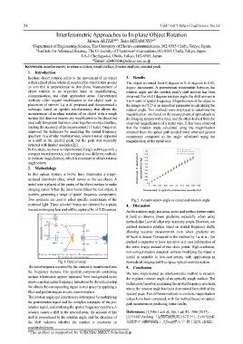
within a fixed plane, where all points of the object rotate around The object is rotated from 0 degrees to 0.16 degrees in 0.01-
an axis that is perpendicular to that plane. Measurement of degree increments. A proportional relationship between the
object rotation is an important issue in manufacturing, rotation angle and the spectral peak’s shift amount has been
communication, and other application areas. Conventional observed. For a 0.01 degrees rotation angle, the shift amount is
methods often require modification to the object such as 5 to 6 units of spatial frequency. Magnification of the object to
placement of mirrors. Lu et al. proposed and demonstrated a the image on CCD is an important parameter in calculating the
technique based on speckle interferometry that allows the rotation angle. Two methods were employed to determine the
measurement of in-plane rotation of an object with a rough magnification: one based on the measurement of optical path of
surface that does not require any modification to the object but the imaging system with a ruler, and the other derived from the
used only two points that were close together on object surface, observed magnification of a metal wire. It has been observed
limiting the accuracy of the measurement [1]. Later, Yang et al. that the rotation angle calculated using the magnification
improved the technique by analyzing the spatial frequency obtained from the optical path yielded lower error and greater
spectrum in a similar interferometer, where rotation appeared consistency compared to the angle calculated using the
as a shift in the spectral peak, but the peak was manually magnification of the metal wire.
detected with limited resolution [2].
In this study, we have re-implemented Yang’s technique with a
compact intereferometer, and compared two different methods
to evaluate magnification, which is necessary to obtain rotation
angle values.
2. Methodology Rotation angle Ω calculated from experimental data (deg)
In this optical system, a HeNe laser illuminates a rough-
surfaced aluminum plate, which serves as the test object. A
metal wire is placed at the center of the object surface to make
imaging easier. When the laser beam strikes the test object, it Rotation angle Ω applied by rotational stage manually (deg)
scatters, generating a range of spatial frequency components.
Two apertures are used to select specific components of the Fig 2. Actual rotation angle vs calculated rotation angle
scattered light. These selected beams are directed by a prism 4. Discussion
toward an imaging lens and will be captured by a CCD camera.
As the rotation angle increases, noise and surface texture make
it hard to observe phase gradients, especially when using
methods like Lu et al.'s that rely on nearby points. However, our
method measures rotation based on spatial frequency shifts,
allowing accurate measurement even when gradients are
difficult to detect. Compared to the method by Lu et al., this
method is expected to have less error as it uses information of
the entire image instead of two close points. High-resolution,
non-contact rotation detection without modifying the object is
useful in unstable or low-cost setups, with applications in
Fig 1. Optical setup. biomedical imaging and free-space optical communication.
The interferogram recorded by the camera is transformed into 5. Conclusion
the frequency domain. The spectral components containing We have implemented an interferometric method to measure
surface information appear separated from background noise the in-plane rotation angle of an optically rough surface. The
due to a spatial carrier frequency introduced by the optical setup. technique is based on examining the spatial frequency spectrum,
We obtain the corresponding signal in real space by applying a where the rotation angle has been determined from shift of the
filter and performing an inverse transformation. spectral peak. Two different methods to evaluate magnification
The rotation angle and direction are determined by multiplying values have been compared, with the method based on optical
the post-rotation signal and the complex conjugate of the pre- path measurement producing better results.
rotation signal, and analyzing the spatial frequency spectrum. A
rotation causes a shift in the spectral peak; the amount of this References: [1] Min Lu et al., Opt. Lett. 42, 1986 (2017).
shift is proportional to the rotation angle, and the direction of [2] YANG Andong 「空間周波数成分に注目した面内回転
the shift indicates whether the rotation is clockwise or 角測定の実験的検証」,電気通信大学 修士論文, (2022).
counterclockwise.
*The author is supported by (GECHA) MEXT Scholarship