Page 11 - 2024S
P. 11

4                                                                 UEC Int’l Mini-Conference No.52


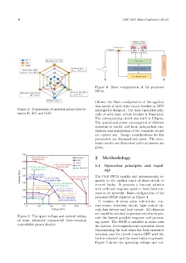
                                                              Figure 4: Basic configuration of the proposed
                                                              SSCB.


                                                              follows: the Basic configuration of the applica-
                                                              tion model of solid state circuit breaker in 100V
            Figure 2: Comparison of material properties be-   microgrid is designed. The basic operation prin-
            tween Si, SiC and GaN                             ciple of solid state circuit breaker is illustrated.
                                                              The corresponding circuit was built in LTspice.
                                                              The operational power consumption of different
                                                              materials is tested, and local independent sim-
                                                              ulations and simulations of the complete circuit
                                                              are carried out. Design considerations for key
                                                              parameters are discussed and given. The simu-
                                                              lation results are illustrated and conclusions are
                                                              given.


                                                              2    Methodology


                                                              2.1   Operation principles and topol-
                                                                    ogy

                                                              The GaN SSCB rapidly and autonomously re-
                                                              sponds to the sudden onset of short-circuit or
                                                              current faults. It presents a low-cost solution
                                                              with sufficient response speed to limit fault cur-
                                                              rents in dc networks. Basic configuration of the
                                                              proposed SSCB depicted in Figure 4.
                                                                It consists of seven main subcircuits: cur-
                                                              rent sensor, detection circuit, logic control cir-
                                                              cuit, fast drivers and load circuit. All elements
                                                              are carefully selected to prompt and timely pro-
            Figure 3: The upper voltage and current ratings   vide the fastest possible response and process-
            of some advanced commercial three-terminal
                                                              ing speed. The SSCB is installed in series with
            controllable power devices
                                                              the system. Its straightforward operation allows
                                                              disconnecting the load when the fault current is
                                                              detected, and the circuit remains OFF until the
                                                              fault is removed and the reset button is pressed.
                                                              Figure 5 shows the operating voltage and cur-
   6   7   8   9   10   11   12   13   14   15   16