
Page 26 - 2024S
P. 26
UEC Int’l Mini-Conference No.52 19
this transient behavior will collapse and the
objective of a first-order transfer behavior will
be obtained. The numerator of equation (2) can
be multiplied out, and equation (4) is received.
n
X
h = a 1 s n−1 + a 2 s n−2 + · · · + a n−1 s + R i (4)
i=1
Considering that all a i are zero, only the sum
of the R i is left, and equation (3) is obtained.
As all a i depend on all R i and T i , the following
optimization problem can be formulated, con-
sidering both reference signals r P and r Q .
n−1
X
min o = a i,P (R i,P , T)s n−i +
i=1
n−1
X
a i,Q (R i,Q , T)s n−i
i=1 (5)
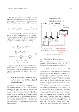
n n Figure 2: Attack Scenario
X X
subject to r P = r i P ∧ r Q = r i Q
i=1 i=1
3.1 Flexibility Region Attack
r min P < r i P < r max P
The inequality constraint of the minimization
∧ r min Q < r i Q < r max Q
problem (5) ensures that r = (r 1 , .., r i , .., r n ) is
Equation (5) is the final bus controller func- in the set REF defined by r min and r max .
tion, where r min and r max represent the flexibil-
ity regions of the DER. This controller does not REF = {r | r min < r i < r max } (6)
operate dynamically but updates every one to The boundaries of the interval are determined
two seconds.
by the DER characteristics and the current state
of the DER; for example, a storage system has
3 Bus Controller Attack sce- a maximal amount of energy that can be stored.
Furthermore, r min and r max are considered to
narios due to DERs signal be set due to optimal considerations, such as
manipulation charging cycles to increase the lifetime of a stor-
age system [8].
The signals transmitted by the DERs Level are In general, the attack aims to manipulate
the flexibility regions r min , r max , and the active the flexibility region signals r min (t) and r max (t)
and reactive power generated or consumed by transmitted by one or more DERs. The result
the DER y i . The values r min and r max repre- is that the optimization is based on a set
sent the lower and upper bounds for the active REF containing solutions that are not feasible,
power, as well as the lower and upper bounds for and the reference signal transmitted by the
the reactive power. In the following, three ma- SPC-Level Controller may not be followed.
licious signal manipulations are considered: i) It is worth mentioning the importance of
enlarging the flexibility region, ii) shrinking the differentiating between the flexibility regions of
flexibility region, iii) maliciously changing power each level. The flexibility regions of the buses,
measurements. SPCs, and the transmission grid operator are